Hydraulically separates boiler and system circuits
The flow difference between the two circuits is absorbed inside the separator; a flow change in one circuit does not affect the other.
Product group · Pressure Vessels
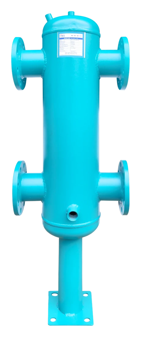
A hydraulic separator balances the flow difference between the boiler circuit and the system circuit, preventing pumps from interfering with each other; the low flow velocity inside the shell also lets free air separate out at the top and sediment collect at the bottom. At Denfor Endüstriyel, we supply hydraulic separators and manifold-integrated packaged separator units, insulated or uninsulated, sized to system flow rate and connection diameters.
Why it matters
It balances the flow difference between the boiler circuit and the system circuit, preventing pumps from interfering with each other.
The flow difference between the two circuits is absorbed inside the separator; a flow change in one circuit does not affect the other.
In multi-pump systems, one pump switching on or off does not disturb the operating point of the pump on the other circuit.
Thanks to the low flow velocity inside the shell, free air separates out at the top while sediment collects at the bottom and can be cleaned out via the drain valve.
When the hydraulic separator and the distribution manifold are combined in a single shell, the need for separate installation in the boiler room disappears.
Types
All three provide flow balancing; what differs is manifold integration and insulation status.
A basic solution installed between the boiler and system circuits that provides hydraulic separation only.
The hydraulic separator and distribution manifold are combined in a single shell, shortening installation time in multi-circuit boiler rooms.
Supplied with an insulation jacket to reduce heat loss; preferred on projects where energy efficiency matters.
Selection criteria
Selection cannot be made without the first two items. The rest determine the manifold and insulation needs.
System flow rate
Shell diameter is determined from the total flow rate of the boiler and system circuits.
m³/h
Number of circuits
The number of circuits to be combined with the manifold determines the need for a packaged type.
count
Working pressure
Must match the system supply pressure.
bar
Insulation need
Insulated or uninsulated, chosen according to heat loss tolerance.
Yes / no
Connection type
Flanged or threaded connection preference.
Connection standard
Installation point and size
Boiler room layout and service clearance.
Installation clearance
It's fine if you don't have all of it. We'll fill in the gaps together with you.
Create a quote requestFAQ
The questions we encounter most often at the hydraulic separator quote stage.
Yes, they serve the same function; by balancing the flow difference between two circuits, they prevent pumps from interfering with each other. The terms are mostly used interchangeably.
On projects where several heating/cooling circuits are fed from the same boiler room, combining the separator and distribution manifold in a single shell reduces installation time and space requirements.
The aim is to keep the flow velocity inside the shell low (typically around 0.1-0.2 m/s); this, based on the system flow rate, determines the shell diameter.
Sediment is periodically drained from the discharge valve at the bottom of the shell; this can be done quickly without stopping the system.
No. While our office is on Istanbul's Anatolian side (Ataşehir), we supply and ship across Istanbul's European side, the surrounding provinces and the Marmara region, and Turkey as a whole — covering your equipment end to end, from a single source.
Next step
Share the flow rate of your boiler and system circuits, and let's work out the right hydraulic separator for your boiler room together.
Related products
Complementary equipment you may need for your project.